2025.03.04.
15:14

Írta: harsanyireka

KY-037 Hangérzékelő

KY-037 Hangérzékelő modul, Arduino, AVR, PICKY-037 Sound Module Pinout

ADATLAP

Connections Arduino:

// digital signal =[Pin 3]

+V =[Pin 5V]

GND =[Pin GND]

analog signal =[Pin 0]

KY-037 Sound Module Circuit

ARDUINO KÓD - analóg

  /*   
modified on June 5, 2018
by Arduino Examples from arduino.cc/en/Tutorial/ReadAnalogVoltage
Home 
*/ 

void setup() {
  // initialize serial communication at 9600 bits per second:
  Serial.begin(9600);
}

// the loop routine runs over and over again forever:
void loop() {
  // read the input on analog pin 0:
  int sensorValue = analogRead(A0);
  // print out the value you read:
  Serial.println(sensorValue);
} 

ARDUINO KÓD -digitális

/*   
modified on Spe 2, 2020
by MohammedDamirchi
Home 
*/ 
const int mic =  8;
void setup() {
  // initialize serial communication at 9600 bits per second:
  Serial.begin(9600);
  // initialize the digital pin as an input:
  pinMode(mic, INPUT);
}

void loop() {
  // check if the mic digitalout is high.
  if (digitalRead(mic) == HIGH) {
    Serial.println("hearing something");
  }
}


forrás:

https://electropeak.com/learn/interfacing-ky-037-sound-sensor-with-arduino/?srsltid=AfmBOopCSYTjXWkHrp5BxuTX_sOiH2Kr7Out_j1yx19lopKO3InRPn8D

Szólj hozzá!

2025.03.04.
15:04

Írta: harsanyireka

HW-504 joystick

0 Joystick with Arduino bb.png

A bot kezdőpozíciója a ( x,y:511,511). Ha a botot az X tengelyen az egyik végétől a másikig mozgatjuk, az X értékek 0 és 1023 között változnak, és hasonló történik, ha az Y tengely mentén mozgatjuk. Ugyanezeken a vonalakon ezen értékek kombinációjából leolvasható a pálca pozíciója a felső félgömb bármely pontján.

Nézzük meg ezeket az értékeket soros porton!

ARDUINO KÓD

#define joyX A0
#define joyY A1
 
void setup() {
Serial.begin(9600);
}
 
void loop() {
// put your main code here, to run repeatedly:
xValue = analogRead(joyX);
yValue = analogRead(joyY);
 
//print the values with to plot or view
Serial.print(xValue);
Serial.print("\t");
Serial.println(yValue);
}


forrás:

https://exploreembedded.com/wiki/Analog_JoyStick_with_Arduino 


Szólj hozzá!

2025.03.04.
14:42

Írta: harsanyireka

HC-SR04 távolság szenzor

Az érzékelőnek 4 tüskéje van. A VCC és a GND az Arduino 5V és GND pinjeire megy, a Trig és Echo pedig bármelyik digitális Arduino tüskéire. A Trig pin segítségével elküldjük az ultrahanghullámot az adóból, és az Echo pin segítségével hallgatjuk a visszavert jelet.

HC-SR04 Ultrasonic Sensor Arduino Connection - Wiring

A szenzor adatlapja:

ARDUINO KÓD

/* Ultrasonic Sensor HC-SR04 and Arduino Tutorial by Dejan Nedelkovski, 
www.HowToMechatronics.com */


// pinek definiálása
const int trigPin = 9;
const int echoPin = 10;

// változók definiálása
long duration;
int distance;


void setup() {

pinMode(trigPin, OUTPUT);
// trigPin-t beáálítjuk kimenetnek

pinMode(echoPin, INPUT);
// echoPin-t beállítjuk bemenetnek

Serial.begin(9600);
// Bekapcsoljuk a serial communication / soros kommunikációt
}


void loop() {

// kikapcsoljuk a trigPin-t
digitalWrite(trigPin, LOW);
delayMicroseconds(2);

// Bekapcsoljuk trigPin-t 10 mikromásodpercre
digitalWrite(trigPin, HIGH);
delayMicroseconds(10);
digitalWrite(trigPin, LOW);

// Kiolvassuk az echoPin-t, a hanghullám utazási ideje mikromásodpercben
duration =
pulseIn(echoPin, HIGH);

// Távolság kiszámítása
distance = duration *
0.034 / 2;

// Soros porton kírjuk
Serial.print("Distance: ");
Serial.println(distance);

}


forrás:

https://howtomechatronics.com/tutorials/arduino/ultrasonic-sensor-hc-sr04/#hc-sr04-hardware-overview 


Szólj hozzá!

2025.03.04.
14:04

Írta: harsanyireka

Arduino + Processing példák

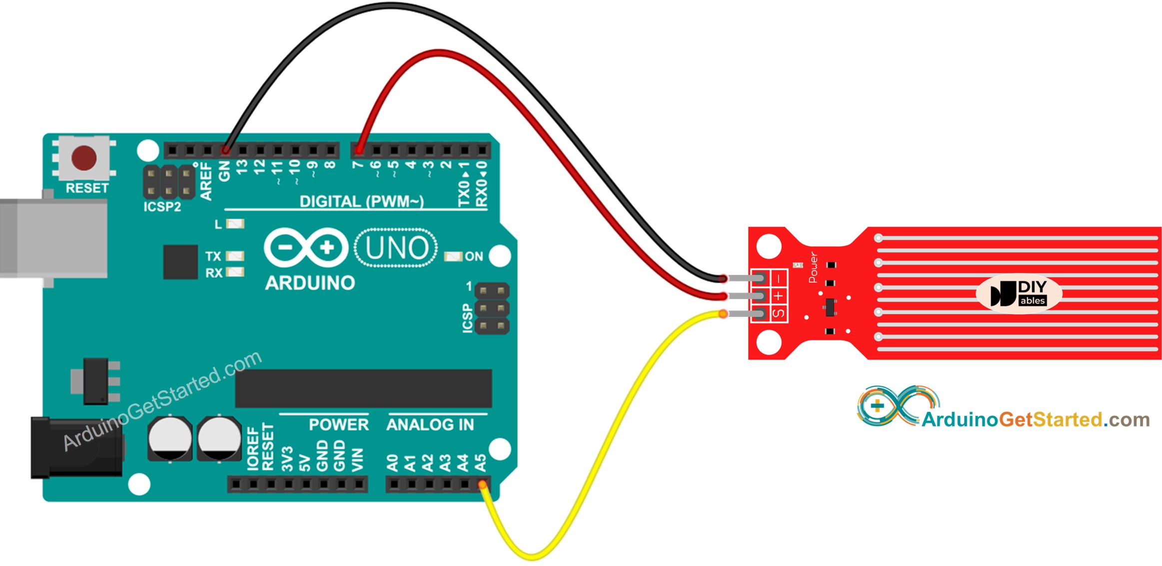
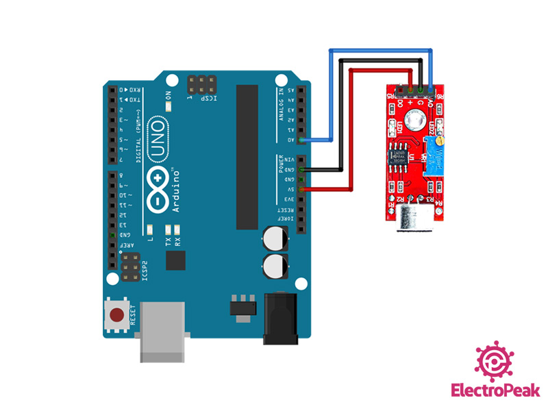
Arduino bekötése: Potméter A0-ba

Arduino Potentiometer - Circuit and Code Example


ARDUINO KÓD

void setup(){
    Serial.begin(9600);
}

void loop(){

 int val = analogRead(0);
   val = map(val, 0, 300, 0, 255);
    Serial.println(val);
delay(50);
}

PROCESSING KÓDOK

1/

import processing.serial.*;

Serial myPort;  // Create object from Serial class
static String val;    // Data received from the serial port
int sensorVal = 0;

void setup()
{
  fullScreen(P3D);
  noStroke();
  fill(204);
  String portName = "COM5";// Change the number (in this case ) to match the corresponding port number connected to your Arduino. 

  myPort = new Serial(this, portName, 9600);
}

void draw()
{
  if ( myPort.available() > 0) {  // If data is available,
  val = myPort.readStringUntil('\n'); 
  try {
   sensorVal = Integer.valueOf(val.trim());
  }
  catch(Exception e) {
  ;
  }
  println(sensorVal); // read it and store it in vals!
  }  
  noStroke(); 
  background(0); 
  float dirY = (sensorVal/ float(height) - 0.5) * 2 * -1;
  float dirX = (mouseX / float(width) - 0.5) * 2;
  directionalLight(204, 204, 204, -dirX, -dirY, -1); 
  translate(width/2 - 100, height/2, 0);  
  translate(200, 0, 0); 
  sphere(200);


  fill(255);
  ellipse(random(width), random(height), 3, 3);

}

2/

import processing.serial.*;

Serial myPort;  // Create object from Serial class
static String val;    // Data received from the serial port
int sensorVal = 0;

void setup()
{
   size(720, 480);
  stroke(255);
  noFill();
  String portName = "COM5";// Change the number (in this case ) to match the corresponding port number connected to your Arduino. 

  myPort = new Serial(this, portName, 9600);
}

void draw()
{
  if ( myPort.available() > 0) {  // If data is available,
  val = myPort.readStringUntil('\n'); 
  try {
   sensorVal = Integer.valueOf(val.trim());
  }
  catch(Exception e) {
  ;
  }
  println(sensorVal); // read it and store it in vals!
  }  
 background(0);
  for (int i = 0; i < 200; i += 20) {
    bezier(sensorVal-(i/2.0), 40+i, 410, 20, 440, 300, 240-(i/16.0), 300+(i/8.0));
  }

}

3/

import processing.serial.*;

Serial myPort;  // Create object from Serial class
static String val;    // Data received from the serial port
int sensorVal = 0;

void setup()
{
   size(720, 480);
   noStroke();
  noFill();
  String portName = "COM5";// Change the number (in this case ) to match the corresponding port number connected to your Arduino. 

  myPort = new Serial(this, portName, 9600);
}

void draw()
{
  if ( myPort.available() > 0) {  // If data is available,
  val = myPort.readStringUntil('\n'); 
  try {
   sensorVal = Integer.valueOf(val.trim());
  }
  catch(Exception e) {
  ;
  }
  println(sensorVal); // read it and store it in vals!
  }  
 background(0);
  // Scale the mouseX value from 0 to 640 to a range between 0 and 175
  float c = map(sensorVal, 0, width, 0, 400);
  // Scale the mouseX value from 0 to 640 to a range between 40 and 300
  float d = map(sensorVal, 0, width, 40,500);
  fill(255, c, 0);
  ellipse(width/2, height/2, d, d);   

}

forrás: https://www.arduino.cc/education/visualization-with-arduino-and-processing/ 

Processing leckék https://processing.blog.hu/ 

Szólj hozzá!

Címkék: processing serial

2024.11.27.
18:07

Írta: harsanyireka

I2C LCD kijelző

lcd.jpg

Ezek az LCD-k ideálisak kizárólag karakterek megjelenítésére. Egy 16×2 karakteres LCD például 32 ASCII karaktert képes megjeleníteni két sorban.

Az adapter középpontjában egy 8 bites I/O bővítő chip - PCF8574 - áll. Ez a chip alakítja át az Arduino I2C-adatokat az LCD-kijelzőhöz szükséges párhuzamos adatokká. A board tartalmaz egy apró trimpotot is, amellyel pontosan beállítható a kijelző kontrasztja. A boardon található egy jumper, amely a háttérvilágítás áramellátását biztosítja. A háttérvilágítás intenzitásának szabályozásához eltávolíthatja a jumper-t, és külső feszültséget kapcsolhat a „LED” feliratú pin-re.

Az I2C LCD kijelzőnek csak négy tűje van. A következő a pinout:

i2c-lcd-display-pinout.webp

A GND egy földelt pin.

A VCC a tápellátás pinje. Csatlakoztasd az Arduino 5V-os kimenetéhez.

Az SDA az I2C adattüske.

Az SCL az I2C órajel pin.


BEKÖTÉS:

wiring-i2c-lcd-display-with-arduino.webp


KÖNYVTÁR TELEPÍTÉSE

Telepítsd a LiquidCrystal_I2C könyvtárat! Ez a könyvtár lehetővé teszi az I2C kijelzők vezérlését a LiquidCrystal könyvtárhoz nagyon hasonló funkciók segítségével.

A könyvtár telepítéséhez navigálj a Sketch > Include Library > Manage Libraries... Sketch > Include Library > Manage Libraries menüpontra... Várd meg, amíg a Library Manager letölti a könyvtárindexet és frissíti a telepített könyvtárak listáját.

manage-libraries.png


Szűrd a keresést a 'liquidcrystal' beírásával. Keresd meg a Marco Schwartz által készített LiquidCrystal I2C könyvtárat. Kattints rá erre a bejegyzésre, majd válaszd a Telepítés lehetőséget.


PÉLDAKÓD

Ezt a példát a Fájl > Példák > Vezeték > i2c_scanner menüpontban találod

File > Examples > Wire > i2c_scanner.


#include <Wire.h>

void setup() {
  Wire.begin();

  Serial.begin(9600);
  while (!Serial); // Leonardo: wait for serial monitor
  Serial.println("\nI2C Scanner");
}

void loop() {
  int nDevices = 0;

  Serial.println("Scanning...");

  for (byte address = 1; address < 127; ++address) {
    // The i2c_scanner uses the return value of
    // the Write.endTransmisstion to see if
    // a device did acknowledge to the address.
    Wire.beginTransmission(address);
    byte error = Wire.endTransmission();

    if (error == 0) {
      Serial.print("I2C device found at address 0x");
      if (address < 16) {
        Serial.print("0");
      }
      Serial.print(address, HEX);
      Serial.println("  !");

      ++nDevices;
    } else if (error == 4) {
      Serial.print("Unknown error at address 0x");
      if (address < 16) {
        Serial.print("0");
      }
      Serial.println(address, HEX);
    }
  }
  if (nDevices == 0) {
    Serial.println("No I2C devices found\n");
  } else {
    Serial.println("done\n");
  }
  delay(5000); // Wait 5 seconds for next scan
}


Miután feltöltötted a kódot, indítsd el a soros monitort 9600 baud-on. Látni fogod az I2C LCD kijelző I2C címét, ezt írd fel mert a kódban szükség lesz rá!

i2c-address-scanner-output.png

// enter the I2C address and the dimensions of your LCD here
LiquidCrystal_I2C lcd(0x3F, 16, 2);


forrás: https://lastminuteengineers.com/i2c-lcd-arduino-tutorial/ 


Szólj hozzá!

süti beállítások módosítása